


ETERNAL CORE TECHNOLOGY

ParaflowEnergy Management Technology System

Paraflow is an unstable multi-energy DC coupling and energy management technology system powered by an Energy Model-Based PINN. It prioritizes renewable energy when multiple sources are available and enables adapted loads to follow available solar power after grid loss.

  • Multi-Energy Allocation
  • Solar-Following Operation
  • Multi-Node Coordination
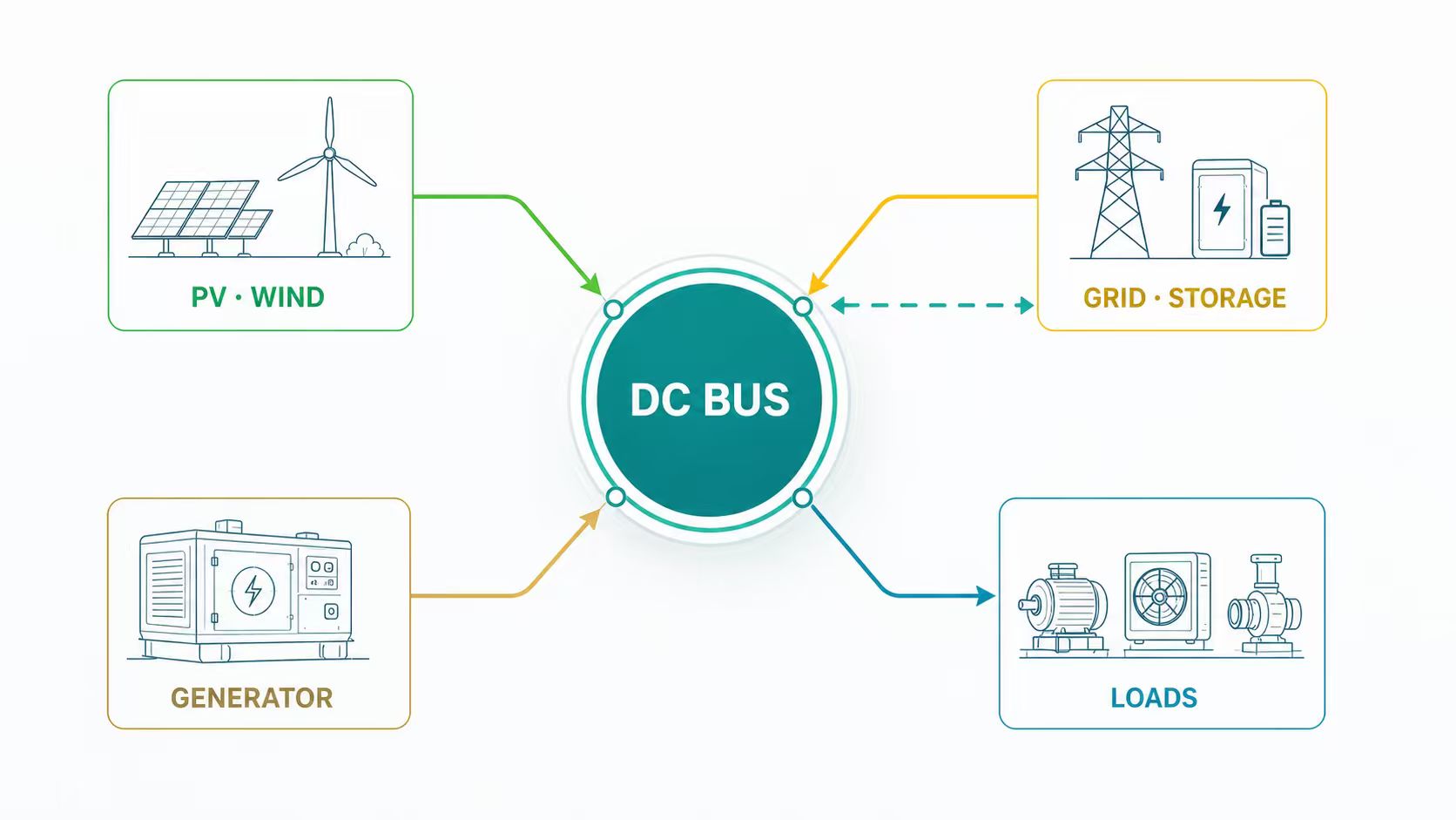
Paraflow DC BUS architecture connecting PV and wind, grid and storage, a generator, and application loads

ONE MODEL · TWO OPERATING OBJECTIVES

Use Renewables First.
Keep Key Functions Available.

The same Energy Model-Based PINN selects a different power target for normal multi-energy operation and for grid-loss operation with one fluctuating source.

01 · MULTI-ENERGY ALLOCATION

Maintain the Load Target.
Fill Only the Gap.

When multiple sources are available, PINN allocates their contributions in real time according to load demand, source capability, and priority strategy.

TargetMaintain the required device output while reducing purchased electricity.
ActionUse PV first; grid, storage, or other sources fill the gap; surplus solar follows project strategy.
ResultEvery additional watt of usable PV reduces the support required from paid energy.
Pload,target = Ppv + Psupport − Ploss
02 · SINGLE-ENERGY FOLLOWING

When the Grid Fails,
Loads Follow Solar Output.

When the grid is lost and storage is absent or inactive, leaving PV as the only fluctuating source, PINN redefines the load target within the energy and physical boundaries available at that moment.

TargetPreserve critical device functions rather than hold rated full power.
ActionAdjust power, speed, frequency, torque, flow, or cooling capacity dynamically.
ResultCreate a practical operating window while usable sunlight remains.
Actual output depends on irradiance, PV capacity, minimum device operating power, and project control boundaries.

SYSTEM EXECUTION

Five Layers.
One Closed Loop.

Paraflow connects global energy intelligence with deterministic device execution, then uses live feedback to correct the next decision cycle.

01 · SYSTEM

Paraflow

Defines the energy, network, safety, and application architecture.

02 · INTELLIGENCE

Energy Model-Based PINN

Selects multi-energy allocation or the available solar-following boundary.

03 · COORDINATION

Downward Vertical Coordination

Distributes dynamic targets to managers, branches, and device nodes.

04 · CONTROL

Local Real-Time Power Control

Executes MPPT, DC/DC, DC BUS regulation, support, curtailment, protection, and fault isolation.

05 · EXECUTION

Devices and Loads

Converts power targets into speed, frequency, torque, flow, or cooling capacity.

Control relationship: PINN and Downward Vertical Coordination are part of Paraflow. Local and device controllers execute their targets, while multi-node allocation follows actual demand rather than equal distribution.

CONTINUOUS OPERATING LOOP
SensePV, wind, grid, storage SOC, diesel, fuel cells, and load demand
IdentifyAvailable energy, constraints, and the current operating state
AllocateGenerate targets and distribute them by actual branch demand
Execute & CorrectConvert, control, protect, and return live node feedback

PINN Target → Energy Managers → Branches and Loads → Real-Time Feedback

APPLICATION VALUE

One Energy Logic.
Multiple Load Types.

The device-control layer turns the same energy target into the physical output required by each adapted application.

01 · VENTILATION

Livestock Ventilation

Preserve essential airflow when grid power is lost but usable solar remains.

02 · COOLING

Solar Air Conditioning

Adjust cooling output to the solar power available at that moment.

03 · AIRFLOW

Industrial Ventilation

Maintain basic air circulation for occupied and process areas.

04 · VARIABLE LOADS

Pumps, Heat Pumps & Motors

Adapt speed, flow, torque, or thermal output within device limits.

Actual capability depends on irradiance, system capacity, device operating limits, and project-specific control boundaries.

ENGINEERING VERIFICATION

Verification by Technical Layer.

Model & Energy AllocationState estimation, target power, source shares, and gap-filling accuracy
Response & DC BUS StabilityOutages, cloud transients, load derating, and voltage stability
Safety & EfficiencyFault isolation, degraded operation, and system-path efficiency
Continuity & CompatibilityCritical-load capability across managers, drives, and application loads

Measured performance must be reported against the relevant prototype, firmware version, and test conditions. Illustrative figures must not replace verified data.

BUILD WITH ETERNAL

Define a Testable Paraflow Configuration.

Share your energy sources, device power, DC BUS parameters, load profile, and operating objectives to define a scalable solution with clear verification boundaries.

Visit Eternal Watt