Introduction
"Full DC architecture" is often misunderstood as a system that eliminates AC power entirely. That's not quite right. What "full DC" actually means is that solar PV power—after MPPT and DC/DC regulation—goes directly into the drive's DC bus, skipping the intermediate step of being inverted to AC and then rectified back to DC.
What's really worth understanding is how solar and grid power couple in real time on the same DC bus to achieve solar priority and grid complement—with the basic solution requiring no batteries for stable operation.
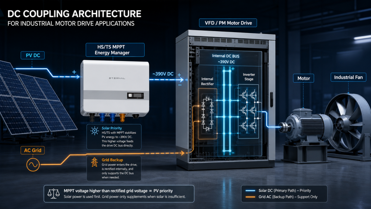
Figure 1 All-DC Architecture with HS/TS MPPT Energizer embedded in VFD DC Bus
A critical clarification right up front: When we say "No Inverter" in the title, we mean no separate solar grid-tied inverter—the expensive, standalone box typically required in AC-coupled solar systems. The VFD's built-in inverter stage that controls motor speed is still there and fully functional; that's how a drive works. What we eliminate is the redundant solar-side inversion-and-rectification loop, not the motor control itself.
Clarifying the Concept: What Is "Real-Time Coupling" on the DC Bus?
Solar and grid power are often understood as a "one-or-the-other" choice. Full DC architecture breaks this switching mindset. Instead, both energy sources are directly superimposed on the drive's DC bus.
Let's clarify the role of each component:
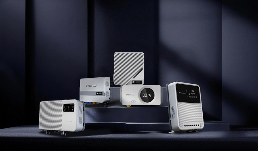
l HS/TS (Eternal) Energizer: This is an MPPT-equipped device that tracks the maximum power point of fluctuating solar PV and stabilizes the output to a voltage matching the drive's DC bus. It is neither a grid-tied inverter nor an ordinary charge controller.
l VFD/Permanent Magnet Motor Drive: Grid power enters the drive through its built-in rectification module and feeds into the same DC bus. No external separate rectifier is required outside the drive.
l DC Bus: This is where solar and grid energy converge, with the output stage then inverting to drive the motor.
To be absolutely clear: there are three possible inverter-related roles in a motor system—(1) a solar grid-tied inverter (AC-coupled), (2) the VFD's internal inverter stage (motor speed control), and (3) the drive's output inversion. Full DC architecture removes (1), reuses (2), and keeps (3) as standard. The title "No Inverter" refers specifically to (1).
The energy paths can be simplified into two streams—note how both solar and grid share the same bus:
Solar Path: PV DC → HS/TS MPPT & DC/DC regulation → Drive DC Bus → Drive Inverter DC/AC → Motor
Grid Complement: Grid AC → Drive Internal Rectification → Drive DC Bus → Drive Inverter DC/AC → Motor
A critical clarification: the motor drive's output stage still performs DC/AC inversion to control the motor—that's inherent to VFD operation and remains unchanged. When we say "No Inverter," we mean no separate solar inverter (the standalone unit used in AC coupling). The value is in eliminating the redundant "invert-to-AC-then-rectify-back" loop on the solar side, not in removing motor control inversion.
Core Control Logic: Bus Voltage Determines Energy Priority
No complex logic decisions or relay switching are needed to automatically achieve "solar priority." The answer lies in the voltage relationship on the DC bus. The HS/TS Energizer stabilizes the solar-side output to a level slightly higher than the grid-rectified bus voltage (illustratively around 390V DC—actual value depends on the drive and system design). Here's what happens:
l When the MPPT-side bus voltage is higher than the grid-rectified bus voltage, solar energy takes priority in feeding the bus, and the load is primarily powered by solar.
l The grid-rectified voltage is slightly lower and remains on standby, only filling the gap when the bus voltage is pulled down by the load and solar cannot independently support it.
l The entire process is naturally driven by the bus voltage differential—it's continuous power superposition, not a mechanical binary switch.
The operational logic is simple: use as much solar as possible, and let the grid fill whatever is missing. If the load needs 100kW and solar is providing 70kW at that moment, the grid immediately supplements about 30kW. The next moment, if solar rises to 90kW, the grid contribution automatically drops to about 10kW. The entire regulation is handled by the bus voltage closed-loop control—smooth and seamless.
Key point: Solar and grid power are not "switched" but "superimposed" on the DC bus. The bus voltage acts both as the "arbiter" of energy priority and the regulating link where the two power sources rise and fall in balance.
From Single Drive to Multiple: On-Demand Distribution in a DC Microgrid
The logic that bus voltage determines priority doesn't just apply to a single device—it extends naturally to multiple devices. DC-side coupling inherently supports multiple drives connected to the same DC bus, forming a DC microgrid. In this configuration, solar is no longer just "supplementing one device's deficit"—it supplies energy to the entire microgrid.
Solar energy flows dynamically to the devices that are running and demanding power at any given moment: wherever there's an active load, solar goes there. Even if some devices are offline, solar output is consumed locally by other active loads within the same microgrid rather than being wasted.
In one sentence: Wherever a drive is running, solar flows there. As long as there's a load running in the microgrid, solar energy has a destination—nothing is wasted.
A note of caution: without specific engineering design, it should not be assumed that any devices can simply share a common bus in parallel. Multi-drive common bus / DC microgrid configurations require electrical matching and protection design based on site conditions. Bus voltage levels, power capacity, isolation, and protection schemes should all be determined by actual engineering requirements.
Operating Principles Under 3 Light Conditions
Breaking down a day's solar variation into three typical states makes it easier to see how DC coupling works dynamically.
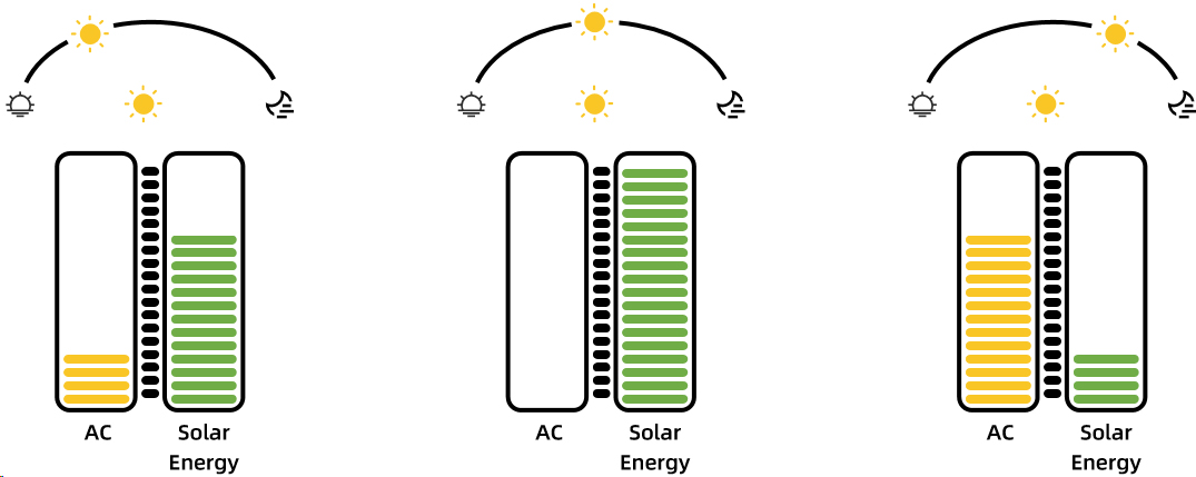
Figure 2 DC Coupling
State 1: Abundant Solar
When irradiance is strong, the HS/TS stabilizes solar power and feeds it into the bus. The bus voltage is pushed up to the solar-side target. The load is essentially powered entirely by solar, while the grid-rectified side sits at a lower voltage and injects almost no power—remaining on standby with near-zero contribution. If instantaneous solar output exceeds load demand, the MPPT adjusts its operating point to match injection power with load consumption—the system consumes locally without feeding back to the grid.
State 2: Insufficient or Fluctuating Solar
During cloudy conditions, overcast skies, or rapidly moving cloud cover, solar output fluctuates up and down. This is precisely where DC coupling demonstrates its greatest value:
l As solar drops and bus voltage trends downward, the grid-rectified side immediately supplements the deficit on the same bus, stabilizing the voltage.
l When solar recovers and bus voltage is pushed back up, grid complement automatically falls back.
l This "supplement–retreat" process is continuous and real-time, driven by the bus voltage closed-loop. The load side barely perceives the shifting energy sources.
Because the grid is always on standby at the bus side to complement, solar fluctuations do not translate into load power fluctuations. This is the fundamental reason the system runs stably without requiring battery buffering.
State 3: No Sunlight
At night or during extended periods without light, the solar side produces nothing. The bus voltage is maintained entirely by grid rectification. The equipment essentially reverts to conventional grid-powered operation, with the drive's internal rectification supplying all power—production continues uninterrupted. When daylight returns and solar picks up, the bus voltage is pushed back up and the system automatically reverts to solar priority—no manual intervention needed.
| Light Condition | Bus Voltage Dominant Source | Solar Share | Grid Share | Control Behavior |
| Abundant solar | Solar side pushes high | High (approaching load demand) | Low (near standby) | Solar independently powers load; grid nearly zero |
| Insufficient/fluctuating | Solar and grid jointly | Medium, varying with light | Real-time deficit filling | Continuous supplement–retreat regulation; load unaware |
| No sunlight | Grid rectification maintains | Zero | Full load power | Equivalent to conventional grid operation; production unaffected |
The above table is a qualitative description based on energy paths. Specific percentages and values in each state depend on actual measurements and specific system selection.
Load Types Require Different Control Strategies
DC coupling addresses "where the energy comes from." The load side cares about "how operating conditions are maintained." Two typical load types need to be distinguished here.
Variable-Speed Loads: Fans and Pumps Can Do Power or Speed Tracking
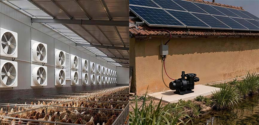
Figure 3 Photovoltaic ventilation system and water pump system
Loads like fans and pumps have a wide adjustable range for speed and power and are insensitive to short-term fluctuations. When solar is abundant, they can be allowed to moderately follow available power, maximizing solar consumption. When solar drops, the grid fills the gap. This flexibility in power tracking / speed tracking makes variable-speed loads naturally suited to the fluctuating nature of solar output.
Constant-Power Loads: Compressors Prioritize Stable Operation
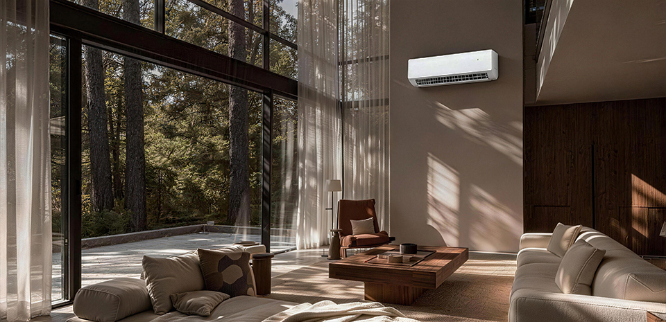
Figure 4 Solar air conditioner system
Constant-power loads like air compressors and refrigeration compressors are the opposite—they require stable power and prioritize operating conditions. They cannot afford to drop speed just because solar fluctuates. The control objective is first to stably meet operating conditions: use as much solar as is available, and let the grid fill the rest in real time on the bus side, ensuring the load always receives the power it needs. Solar here plays the role of "reducing grid draw" rather than sacrificing operating conditions to accommodate light availability.
The difference: Variable-speed loads (fans/pumps) let their operating state "follow" solar, prioritizing power or speed tracking. Constant-power loads (compressors) require solar to "support" the operating conditions—stable production takes priority, with the grid filling any gaps. The same architecture applies to both; the difference lies only in the prioritization of control objectives.
Why the Basic Solution Requires No Batteries
The stable operation of this architecture does not rely on storage as an intermediary because the grid itself is always available as a stable source:
l Solar fluctuation gaps are filled by the grid in milliseconds on the bus side—no battery smoothing needed.
l During no-sun periods, the grid independently supports the load—no battery reserve needed for nighttime operation.
l Batteries are only an optional expansion for specific needs like off-grid operation, peak shaving, or backup power—they are not a prerequisite for the basic architecture.
The basic solution reuses the drive's existing DC bus interface. The grid power path and load control logic remain largely unchanged, minimizing intrusion into the existing system.
Safety Boundaries: Why Reverse Feed and Anti-Islanding Don't Apply
This is an area where safety is often misunderstood. Because solar energy only feeds into the DC bus, and grid power enters through the drive's internal rectification with unidirectional conduction, there is a natural isolation between the DC bus and the AC grid:
l Solar energy cannot flow backward through the rectification unit into the AC grid—no reverse feed / backflow.
l All energy is consumed locally on the load side. This is not a grid-connected generation system—it requires no separate grid-tied inverter and does not involve surplus feed-in or grid-connection approvals.
l "Anti-islanding protection" is a concept for grid-tied inverter scenarios. Since this architecture is not grid-connected, it simply does not apply.
Summary
Full DC architecture is not about eliminating AC—it's about letting solar take a shorter, more efficient path directly to the motor drive's DC bus. The bus voltage itself determines energy priority, enabling solar priority with real-time grid complement, stable operation without batteries, and seamless adaptation to both variable-speed and constant-power loads. Whether you're retrofitting existing drives or designing new systems, this approach offers a practical path to higher solar utilization with minimal system intrusion—and best of all, it removes the standalone solar inverter without touching the VFD's core motor control function.
FAQ
Q1: Is "solar priority, grid complement" achieved through switching?
A1: No. It's driven by the bus voltage differential. The MPPT stabilizes solar side slightly above the grid-rectified voltage, so solar naturally feeds the bus first. When solar drops, grid supplements the deficit in real time—continuous superposition, not mechanical switching.
Q2: Can the system run stably without batteries when solar fluctuates?
A2: Yes. The grid is always on standby at the bus side, filling any gap in milliseconds. Solar fluctuations do not reach the load. Batteries are optional for off-grid or backup needs—not required for stable operation.
Q3: What's the difference in control approach between variable-speed and constant-power loads?
A3:Variable-speed loads (fans, pumps) can follow available solar via power/speed tracking. Constant-power loads (compressors) prioritize stable operation—solar contributes what it can, grid fills the rest. Same architecture, different control priority.
Q4: Does this system feed power back to the grid? Does it require anti-islanding protection?
A4:No to both. Solar only feeds the DC bus; grid enters through unidirectional rectification—natural isolation prevents backflow. All energy is consumed locally. Anti-islanding applies to grid-tied inverters; this architecture is not grid-connected.
Q5: What exactly is the HS/TS Energizer, and how is it different from an inverter or a charge controller?
A5: It's an MPPT device that stabilizes fluctuating PV voltage to match the drive's DC bus. It is not a grid-tied inverter (no grid connection) and not a charge controller (no battery charging). Its sole job is to feed solar into the VFD bus at the right voltage.
Q6: What does "No Inverter" mean in the title if the VFD already has an internal inverter stage?
A6: "No Inverter" refers to the standalone solar grid-tied inverter used in AC-coupled systems—that's eliminated. The VFD's internal inverter (which controls motor speed) remains fully functional. We remove the solar conversion inverter, not the motor control inverter.